5962-9669001HUA データシートの表示(PDF) - Austin Semiconductor
部品番号
コンポーネント説明
メーカー
5962-9669001HUA Datasheet PDF : 26 Pages
| |||
Austin Semiconductor, Inc.
FLASH
AS29F010
selected for erasing are protected, DQ6 toggles for
approximately 100µs, then returns to reading array data. If not
all selected sectors are protected, the Embedded Erase
algorithm erases the unprotected sectors, and ignores the
selected sectors that are protected.
If a program address falls within a protected sector, DQ6
toggles for approximately 2µs after the program command
sequence is written, then returns to reading array data.
The Write Operation Status table shows the outputs for
Toggle Bit I on DQ6. Refer to Figure 4 for the toggle bit
algorithm, and to the Toggle Bit Timings figure in the “AC
Characteristics” section for the timing diagram.
Under this condition, the device halts the operation, and when
the operation has exceeded the timing limits, DQ5 produces a
“1.”
Under both these conditions, the system must issue the
reset command to return the device to reading array data.
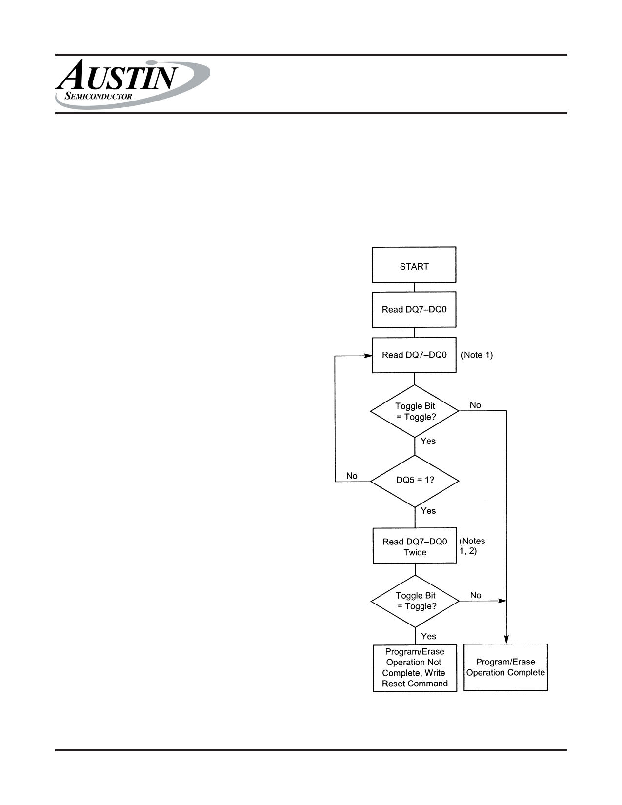
FIGURE 4: TOGGLE BIT ALGORITHM
Reading Toggle Bit DQ6
Refer to Figure 4 for the following discussion. Whenever
the system initially begins reading toggle bit status, it must
read DQ7-DQ0 at least twice in a row to determine whether a
toggle bit is toggling. Typically, a system would note and store
the value of the toggle bit after the first read. After the second
read, the system would compare the new value of the toggle bit
with the first. If the toggle bit is not toggling, the device has
completed the program or erase operation. The system can
read array data on DQ7-DQ0 on the following read cycle.
However, if after the initial two read cycles, the system
determines that the toggle bit is still toggling, the system also
should note whether the value of DQ5 is high (see the section
on DQ5). If it is, the system should then determine again whether
the toggle bit is toggling, since the toggle bit may have stopped
toggling just as DQ5 went high. If the toggle bit is no longer
toggling, the device has successfully completed the program
or erase operation. If it is still toggling, the device did not
complete the operation successfully, and the system must write
the reset command to return to reading array data.
The remaining scenario is that the system initially
determines that the toggle bit it toggling and DQ5 has not gone
high. The system may continue to monitor the toggle bit and
DQ5 through successive read cycles, determining the status as
described in the previous paragraph. Alternatively, it may
choose to perform other system tasks. In this case, the system
must start at the beginning of the algorithm when it returns to
determine the status of the operation (top of Figure 4).
DQ5: Exceeded Timing Limits
DQ5 indicates whether the program or erase time has
exceeded a specified internal pulse count limit. Under these
conditions DQ5 produces a “1.” This is a failure condition that
indicates the program or erase cycle was not successfully
completed.
The DQ5 failure condition may appear if the system tries to
program a “1” to a location that is previously programmed to
“0.” Only an erase operation can change a “0” back to a “1.”
NOTE:
1) Read toggle bit twice to determine whether or not it is toggling. See
text.
2) Recheck toggle bit because it may stop toggling as DQ5 changes to
“1”. See text.
AS29F010
Rev. 2.3 12/08
11
Austin Semiconductor, Inc. reserves the right to change products or specifications without notice.
Share Link: 