PHD78NQ03LT データシートの表示(PDF) - NXP Semiconductors.
部品番号
コンポーネント説明
メーカー
PHD78NQ03LT Datasheet PDF : 12 Pages
| |||
NXP Semiconductors
PHD78NQ03LT
N-channel TrenchMOS logic level FET
4. Limiting values
Table 4. Limiting values
In accordance with the Absolute Maximum Rating System (IEC 60134).
Symbol Parameter
Conditions
VDS
VDGR
VGS
ID
drain-source voltage
drain-gate voltage
gate-source voltage
drain current
Tj ≥ 25 °C; Tj ≤ 175 °C
RGS = 20 kΩ; Tmb ≥ 25 °C; Tmb ≤ 175 °C
VGS = 5 V; Tmb = 100 °C
VGS = 10 V; Tmb = 100 °C; see Figure 1
VGS = 10 V; Tmb = 25 °C; see Figure 1;
see Figure 3
IDM
peak drain current
Ptot
total power dissipation
Tstg
storage temperature
Tj
junction temperature
Source-drain diode
VGS = 5 V; Tmb = 25 °C
tp ≤ 10 µs; pulsed; Tmb = 25 °C; see Figure 3
Tmb = 25 °C; see Figure 2
IS
source current
ISM
peak source current
Avalanches ruggedness
Tmb = 25 °C
tp ≤ 10 µs; pulsed; Tmb = 25 °C
EDS(AL)S
non-repetitive
VGS = 10 V; Tj(init) = 25 °C; ID = 32 A; Vsup ≤ 25 V;
drain-source avalanche unclamped; RGS = 50 Ω; tp = 0.17 ms
energy
Min Max Unit
-
25
V
-
25
V
-20 20
V
-
46.9 A
-
57.5 A
-
75
A
-
66.4 A
-
240 A
-
107 W
-55 175 °C
-55 175 °C
-
75
A
-
240 A
-
100 mJ
120
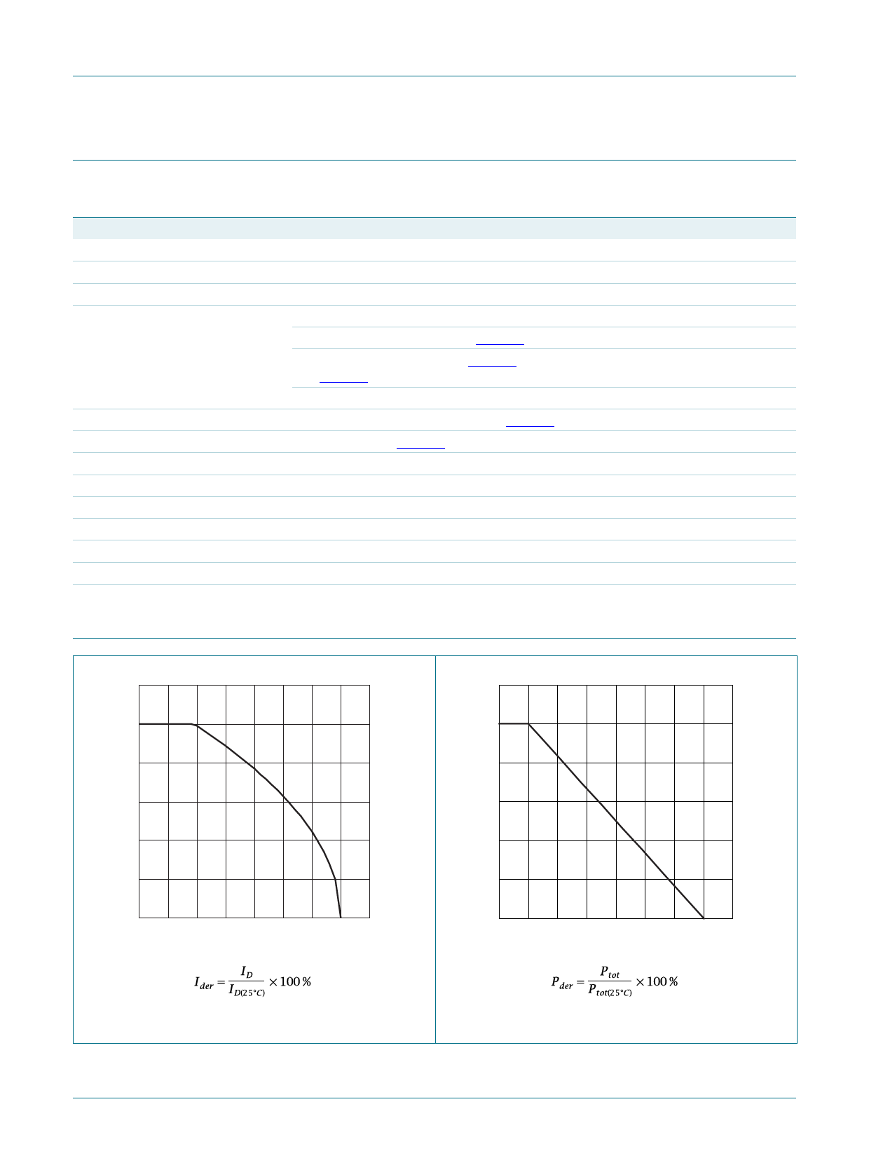
Ider
(%)
80
003aaa755
120
Pder
(%)
80
03aa16
40
40
0
0
50
100
150
200
Tmb (°C)
0
0
50
100
150
200
Tmb (°C)
Fig 1. Normalized continuous drain current as a
function of mounting base temperature
Fig 2. Normalized total power dissipation as a
function of mounting base temperature
PHD78NQ03LT_6
Product data sheet
Rev. 06 — 11 June 2009
© NXP B.V. 2009. All rights reserved.
3 of 12
Share Link: 