STR-A6100 データシートの表示(PDF) - Sanken Electric co.,ltd.
部品番号
コンポーネント説明
メーカー
STR-A6100 Datasheet PDF : 26 Pages
| |||
STR-A6100 Series
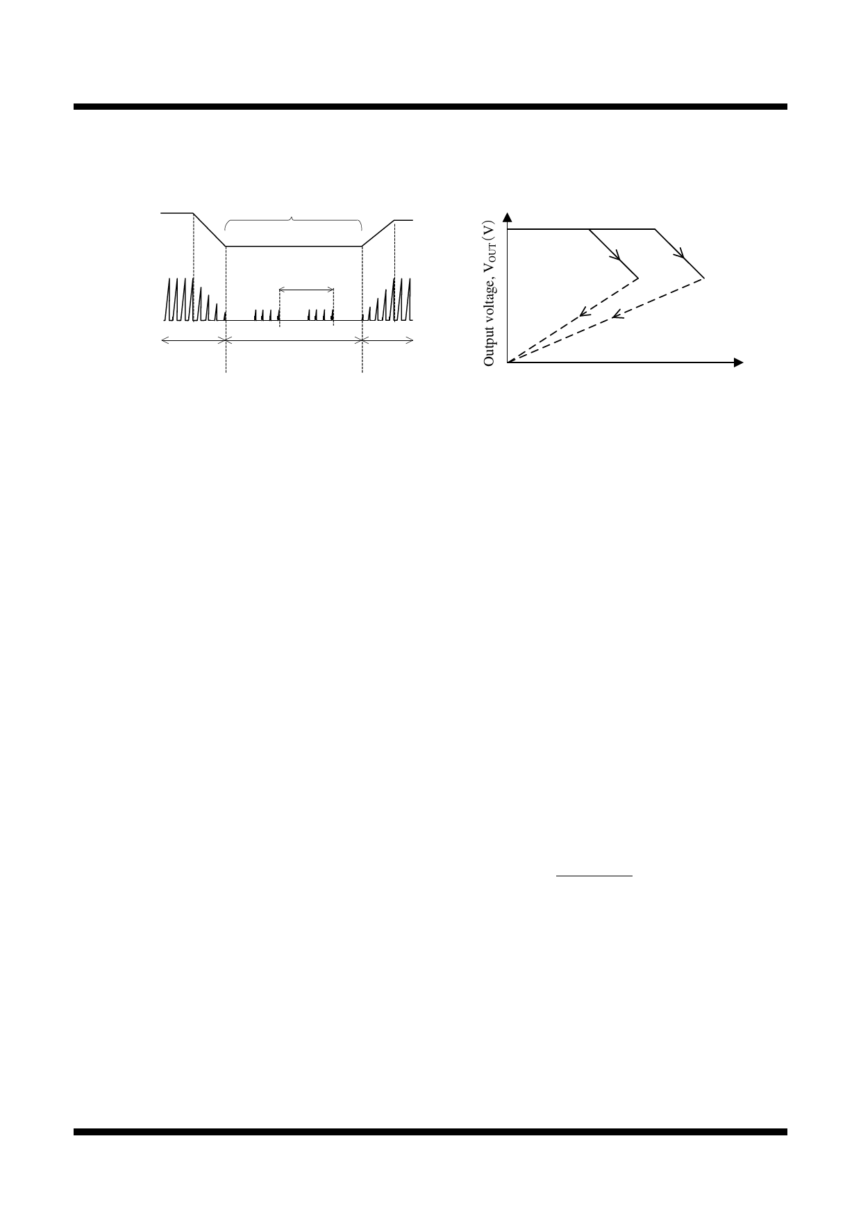
just a few kilohertz. Because the IC suppresses the peak
drain current well during burst mode, audible noises can
be reduced.
Output current,
IOUT
Burst oscillation
Drain current,
ID
Normal
operation
Below several kHz
Standby
operation
Normal
operation
Figure 9-6 Auto Standby mode timing
9.6 Auto Bias Function (STR-A61××)
STR-A61×× includes the auto bias function. The
function becomes active during burst oscillation mode.
When VCC pin voltage decreases to the Auto Bias
Threshold Voltage, VCC(BIAS) = 10.6 V, during burst
oscillation mode, the IC shifts to PRC operation so that
VCC pin voltage does not decrease. As a result, the IC
achieves stable standby operation.
However, if the Bias Assist function is always
activated during steady-state operation including
standby mode, the power loss increases. Therefore, the
VCC pin voltage should be more than VCC(BIAS), for
example, by adjusting the turns ratio of the auxiliary
winding and secondary winding and/or reducing the
value of R2 in Figure 10-2 (refer to Section 10.1
Peripheral Components for a detail of R2).
9.7 Overcurrent Protection Function (OCP)
Overcurrent Protection Function (OCP) detects each
drain peak current level of a power MOSFET on
pulse-by-pulse basis, and limits the output power when
the current level reaches to OCP threshold voltage,
VOCP(TH) = 0.77 V (1.13 V for STR-A61××M and
STR-A6153E).
Figure 9-7 shows the output characteristics. When
OCP becomes active, the output voltage decreases and
the auxiliary winding voltage, VD decreases in
proportion to the output voltage.
When VCC pin voltage decreases to VCC(OFF) = 10 V,
the control circuit stops operation by UVLO circuit, and
reverts to the state before startup. After that, VCC pin
voltage is increased by Startup Current, ISTARTUP. When
VCC pin voltage increases to VCC(ON) = 17.5 V, the IC
restarts the operation. Thus the intermittent operation by
UVLO is repeated in OCP operation.
The IC usually has some propagation delay time. The
steeper the slope of the actual drain current at a high AC
input voltage is, the larger the actual peak of drain
current is. As a result, the detection voltage becomes
higher than VOCP(TH). Thus, the output current depends
on the AC input voltage in OCP operation (refer to
Figure 9-7).
Low AC
input voltage
High AC
input voltage
Output current, IOUT(A)
Figure 9-7 Output characteristic curve
When the multi outputs transformer is used, there is the
case that the auxiliary winding voltage, VD does not
decrease and the intermittent operation is not started,
even if output voltage decreases in OCP operation. This
is due to the poor coupling of transformer. In this case,
the overload protection (OLP) becomes active. (refer to
Section 9.8.)
9.8 Overload Protection (OLP)
Figure 9-8 shows the FB/OLP pin peripheral circuit.
Figure 9-9 shows the OLP operational waveforms.
When the peak drain current of ID is limited by OCP
operation, the output voltage, VOUT, decreases and the
feedback current from the secondary photo-coupler
becomes zero. Thus, the feedback current, IFB, charges
C3 connected to the FB/OLP pin and the FB/OLP pin
voltage increases. When the FB/OLP pin voltage
increases to VFB(OLP) = 7.2 V or more for the OLP delay
time, tDLY or more, the OLP function is activated and the
IC stops switching operation. tDLY is calculated using
Equation (3).
t DLY
C4
×
(VOLP VZ )
I OL P
(3)
there,
tDLY: OLP delay time
VZ: zener voltage of zener diode, DZ1
IOLP: FB/OLP Pin Source Current in OLP Operation is
− 26 µA
After the switching operation stops, VCC pin voltage
decreases to Operation Stop Voltage VCC(OFF) = 10 V and
the intermittent operation by UVLO is repeated.
This intermittent operation reduces the stress of parts
such as power MOSFET and secondary side rectifier
diode. In addition, this operation reduces power
STR-A6100 - DS Rev.2.1
SANKEN ELECTRIC CO.,LTD.
16
Jun. 05, 2014
Share Link: 