MAX6876 データシートの表示(PDF) - Maxim Integrated
部品番号
コンポーネント説明
メーカー
MAX6876 Datasheet PDF : 39 Pages
| |||
PIN
7
8
9
10
11
12
13, 23
14
15
16
17
18
19
20
21
22
EEPROM-Programmable, Quad,
Power-Supply Tracker/Sequencer Circuit
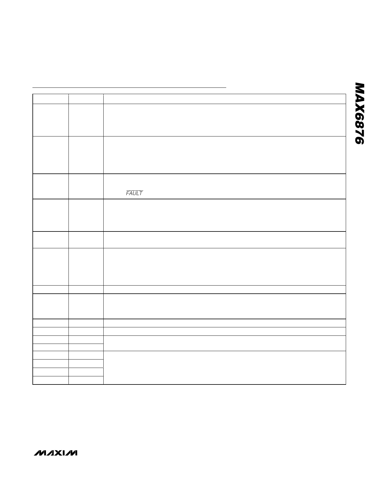
Pin Description (continued)
NAME
OC
REM
FAULT
RESET
ENABLE
MARGIN
N.C.
MR
SDA
SCL
A0
A1
PG1
PG2
PG3
PG4
FUNCTION
Active-Low, Open-Drain Overcurrent Output. OC asserts low if any monitored IN_ to OUT_ voltage
falls out of the selected percentage of the IN_ voltage range (VTH_OC) for more than the programmed
tOC. OC monitoring begins only after supply tracking or sequencing has been completed and is
disabled during power-down operation.
Open-Drain Bus Removal Output. REM signals when it is safe to remove the card after a controlled
track/sequence-down operation. REM goes high impedance when all VOUT_ < VTH_PL. REM requires
an external pullup resistor. In master/slave mode, REM can be ORed together (the common REM
connection remains low if any VOUT_ > VTH_PL threshold) (see the Typical Application Circuit and the
Bus Removal Output (REM) section).
Active-Low, Open-Drain Tracking Fault Alert Output or Input. FAULT asserts low if a tracking failure is
present for longer than the specified fault period or if tracking voltages fails by more than ±250mV
(see the FAULT section).
Active-Low, Open-Drain Reset or Power-Good Output. RESET is low during power-up and power-
down tracking. RESET goes high after all selected OUT_ outputs exceed their selected thresholds
and the reset timeout period tRESET has expired. The reset timeout period is internally selectable.
RESET requires an external pullup resistor.
Logic ENABLE Input. ENABLE must be high to enable voltage tracking/sequencing power-up
operation. OUT_ begins tracking down when ENABLE is low. Connect to ABP if not used.
Active-Low Margin Input. The MARGIN function allows systems to be tested with supply voltages
outside their normal ranges without affecting supply tracking/sequencing or reset states. MARGIN
functionality is usually enabled after systems have powered up in normal mode. The MARGIN
functionality is disabled (returns to normal monitoring mode) after MARGIN returns high. MARGIN is
internally pulled up to ABP through a 100kΩ resistor.
No Connection. Not internally connected.
Active-Low Manual Reset Input. When MR is low, RESET goes low and remains asserted for the
selected timeout period after MR is pulled high. MR is internally pulled up to ABP through a 100kΩ
resistor.
Serial-Interface Data Input/Output (Open-Drain). SDA requires an external pullup resistor.
Serial-Interface Clock Input. SCL requires an external pullup resistor.
Serial-Interface Address Inputs. The inputs allow up to four MAX6876 devices to be addressed when
sharing a common data bus. A1 and A0 should be connected to GND or ABP.
Power-Good Output, Open-Drain. Each PG_ output signals when its monitored OUT_ voltage is within
the selected percentage of the IN_ voltage range (VTH_PG). PG_ is low until OUT_ exceeds the
programmable threshold (VTH_PG) for more than tPOK. PG_ outputs are open-drain and require
external pullups if used.
______________________________________________________________________________________ 11
Share Link: 