MPU-9150 データシートの表示(PDF) - Unspecified
部品番号
コンポーネント説明
メーカー
MPU-9150 Datasheet PDF : 50 Pages
| |||
MPU-9150 Product Specification
Document Number: PS-MPU-9150A-00
Revision: 4.3
Release Date: 9/18/2013
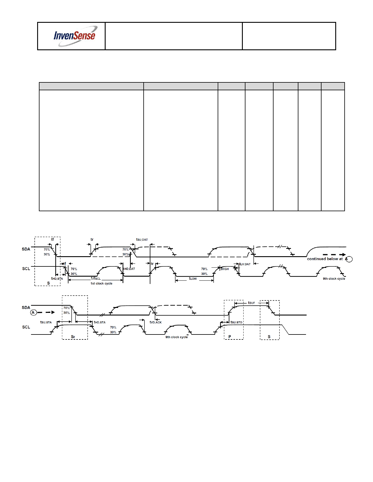
6.8 I2C Timing Characterization
Typical Operating Circuit of Section 7.2, VDD = 2.375V-3.465V, VLOGIC= 1.8V±5% or VDD, TA = 25°C
Parameters
I2C TIMING
fSCL, SCL Clock Frequency
tHD.STA, (Repeated) START Condition Hold
Time
tLOW, SCL Low Period
tHIGH, SCL High Period
tSU.STA, Repeated START Condition Setup
Time
tHD.DAT, SDA Data Hold Time
tSU.DAT, SDA Data Setup Time
tr, SDA and SCL Rise Time
tf, SDA and SCL Fall Time
tSU.STO, STOP Condition Setup Time
tBUF, Bus Free Time Between STOP and
START Condition
Cb, Capacitive Load for each Bus Line
tVD.DAT, Data Valid Time
tVD.ACK, Data Valid Acknowledge Time
Conditions
I2C FAST-MODE
Cb bus cap. from 10 to 400pF
Cb bus cap. from 10 to 400pF
Min
Typical
0.6
1.3
0.6
0.6
0
100
20+0.1Cb
20+0.1Cb
0.6
1.3
< 400
Max
400
300
300
0.9
0.9
Units
kHz
µs
µs
µs
µs
µs
ns
ns
ns
µs
µs
pF
µs
µs
Notes
I2C Bus Timing Diagram
Proprietary and Confidential
18 of 50
Share Link: 