1N5820(2006) データシートの表示(PDF) - ON Semiconductor
部品番号
コンポーネント説明
メーカー
1N5820 Datasheet PDF : 8 Pages
| |||
1N5820, 1N5821, 1N5822
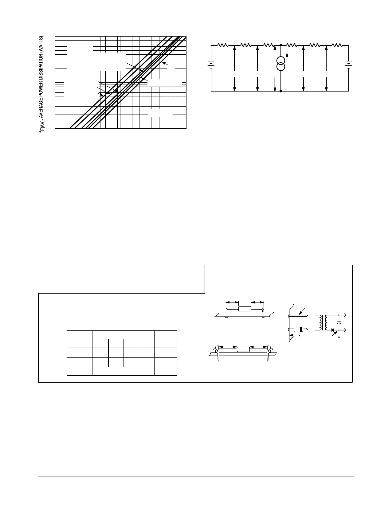
10
7.0
5.0
SINE WAVE
3.0
2.0
I(FM)
I(AV)
+
p
(Resistive
Load)
1.0
0.7
NJ Capacitive
Loads
5.0
10
20
0.5
0.3
0.2
dc
SQUARE WAVE
TJ ≈ 125°C
0.1
0.1
0.2 0.3 0.5 0.7 1.0
2.0 3.0 5.0 7.0 10
IF(AV), AVERAGE FORWARD CURRENT (AMP)
Figure 6. Forward Power Dissipation 1N5820−22
NOTE 4 − APPROXIMATE THERMAL CIRCUIT MODEL
RqS(A)
RqL(A)
RqJ(A)
TA(A)
TL(A)
TC(A)
TJ
RqJ(K
)
PD
RqL(K)
RqS(K)
TA(K)
TC(K)
TL(K)
Use of the above model permits junction to lead thermal
resistance for any mounting configuration to be found. For
a given total lead length, lowest values occur when one side
of the rectifier is brought as close as possible to the heat sink.
Terms in the model signify:
TA = Ambient Temperature
TC = Case Temperature
TL = Lead Temperature
TJ = Junction Temperature
RqS = Thermal Resistance, Heatsink to Ambient
RqL = Thermal Resistance, Lead−to−Heatsink
RqJ = Thermal Resistance, Junction−to−Case
PD = Total Power Dissipation = PF + PR
PF = Forward Power Dissipation
PR = Reverse Power Dissipation
(Subscripts (A) and (K) refer to anode and cathode sides,
respectively.) Values for thermal resistance components
are:
RqL = 42°C/W/in typically and 48°C/W/in maximum
RqJ = 10°C/W typically and 16°C/W maximum
The maximum lead temperature may be found as follows:
TL = TJ(max) * n TJL
where n TJL [ RqJL · PD
NOTE 5 — MOUNTING DATA
Data shown for thermal resistance junction−to−ambient (RqJA)
for the mountings shown is to be used as typical guideline values
for preliminary engineering, or in case the tie point temperature
cannot be measured.
TYPICAL VALUES FOR RqJA IN STILL AIR
Mounting
Method
Lead Length, L (in)
1/8 1/4 1/2 3/4
1
50 51 53 55
2
58 59 61 63
3
28
RqJA
°C/W
°C/W
°C/W
Mounting Method 1
Mounting Method 3
P.C. Board where available
P.C. Board with
copper surface is small.
2−1/2, x 2−1/2,
L
L
ÉÉÉÉÉÉÉÉÉÉÉÉÉÉ ÉÉÉÉ Mounting Method 2
ÉÉÉÉÉÉÉÉÉÉÉÉÉÉÉÉÉ L
L
copper surface.
L = 1/2″
BOARD GROUND
PLANE
VECTOR PUSH−IN
TERMINALS T−28
http://onsemi.com
6
Share Link: 