LC74761(1996) データシートの表示(PDF) - SANYO -> Panasonic
部品番号
コンポーネント説明
メーカー
LC74761 Datasheet PDF : 20 Pages
| |||
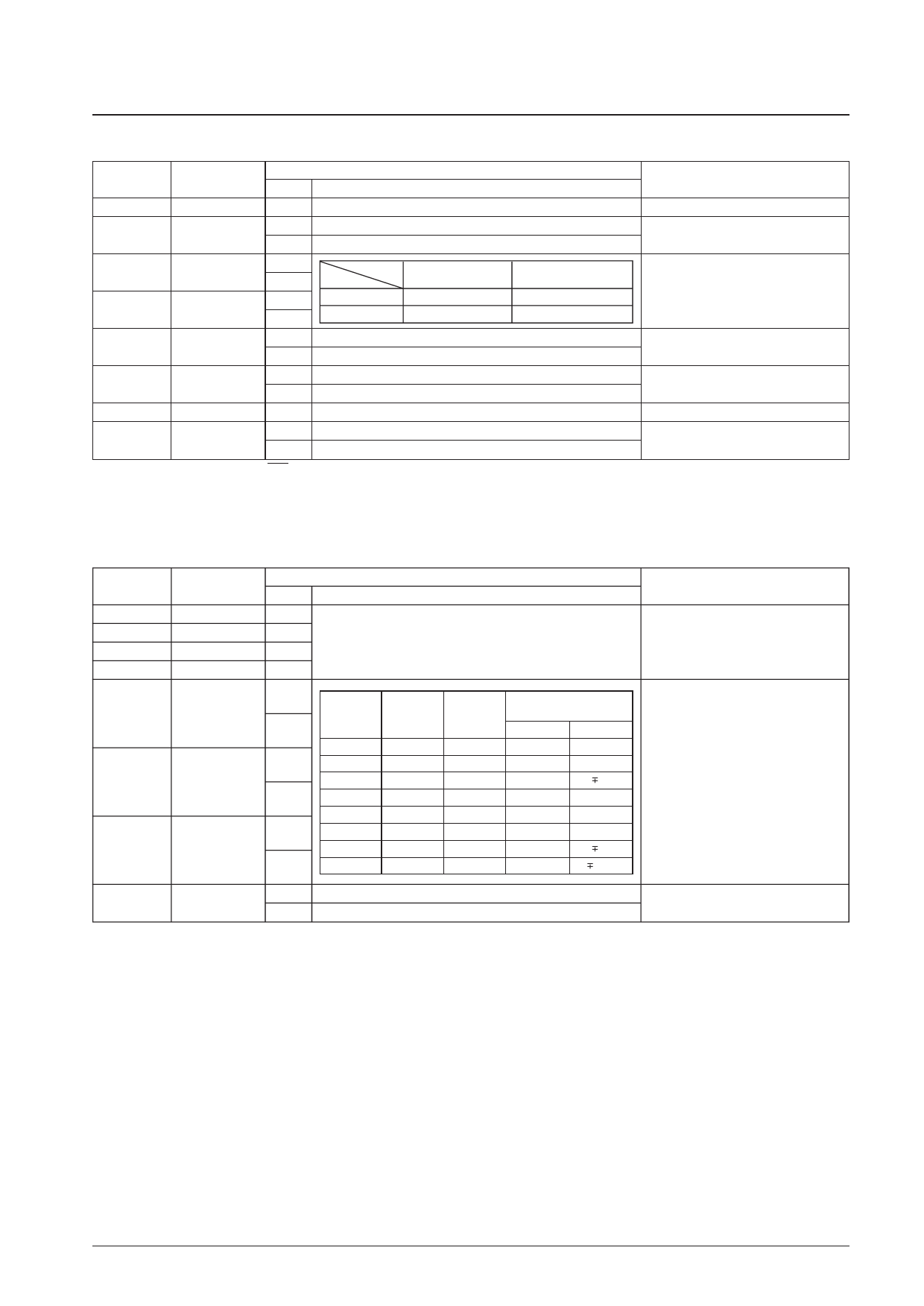
LC74761, 74761M
Second byte
DA0 to DA7
7
6
5
Register name
—
TST
CHAL
State
0
0
1
0
1
0
4
BKL
1
Register content
Function
Second byte identification code
Normal operation
Test mode
Sets the character intensity level to about 85 IRE (bright white).
Sets the character intensity level to about 72 IRE (white with a
touch of grey).
Sets the blanking intensity level to about 3 IRE (a deep black
as a frame level).
Sets the blanking intensity level to about 13 IRE (a dark grey
as a frame level).
0
RSL1
RSL0
Intensity level
Amplitude
3
RSL1
1
0
0
About 15 IRE
About 60 IRE
0
1
About 30 IRE
About 60 IRE
0
1
0
About 45 IRE
About 60 IRE
2
RSL0
1
1
1
About 55 IRE
About 65 IRE
0
Normal CVout output
1
CVoutmt
1
CVout pedestal level output
0
Selects XTAL1
0
XTALsel
1
Selects XTAL2
Note: When the chip is reset by the RST pin, the register states (bits) are all cleared to 0.
Note
Test mode should not be used. This bit
should always be zero.
Switches the character intensity level.
Switches the blanking intensity level.
Switches the background intensity level.
Switches the oscillator circuit
7 COMMAND6: Display Control Setting Command 3
First byte
DA0 to DA7
7
6
5
4
3
2
1
0
Register name
—
—
—
—
MOD3
MOD2
MOD1
MOD0
State
1
1
1
0
0
1
0
1
0
1
0
1
Register content
Function
The command 6 identification code:
sets display control parameters.
Sets Fsc to 3.58 MHz.
Sets Fsc to 4.43 MHz.
Sets the color mode to NTSC.
Sets the color mode to PAL.
Sets the number of scan lines to 525 lines.
Sets the number of scan lines to 625 lines.
Sets the mode to a mode other than SECAM.
Sets the mode to SECAM mode.
Note
The logical or of this bit and the Fsc
switching input pin (pin 14) is used.
The logical or of this bit and the color
mode switching input pin (pin 13) is
used.
The logical or of this bit and the scan
line count switching input pin (pin 12) is
used.
The logical or of this bit and the mode
switching input pin (pin 11) is used.
No. 4846-11/20
Share Link: 