MAX15048 データシートの表示(PDF) - Maxim Integrated
部品番号
コンポーネント説明
メーカー
MAX15048 Datasheet PDF : 31 Pages
| |||
MAX15048/MAX15049
Triple-Output Buck Controllers
with Tracking/Sequencing
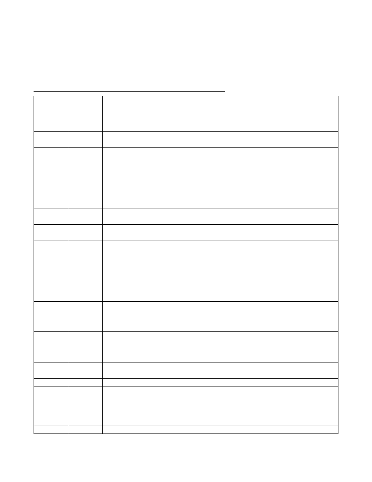
Pin Description (continued)
PIN
NAME
FUNCTION
Controller Power-Good Output. Pull up PGOOD with a resistor to a positive voltage below 5.5V.
12
PGOOD
For the MAX15048, PGOOD output releases when all three VFB_ voltages are above 0.55V. For the
MAX15049, PGOOD output releases when all three controllers are out of prebias and all three VFB_
voltages are above 0.55V.
13
COMP1
Controller 1 Transconductance Error-Amplifier Output. Connect COMP1 to the compensation
feedback network of output 1.
14
FB1
Controller 1 Feedback Regulation Point. Connect to the center tap of a resistive voltage-divider from
the converter output to SGND to set the output voltage. The FB1 voltage regulates to 0.6V (typ).
Controller 1 Enable Input. For tracking (MAX15048), EN1 must be above 0.6V, VEN-TH, for the PWM
15
EN1
controller to start outputs 1, 2, and 3. Controller 1 is the master. Use the master as the highest output
voltage in a coincident tracking configuration. For the MAX15049, EN1 must be above 0.6V for the
PWM controller to start output 1.
16
BST1 Controller 1 High-Side Gate-Driver Supply. Connect a 0.1FF ceramic capacitor from BST1 to LX1.
17
DH1 Controller 1 High-Side Gate-Driver Output. DH1 drives the gate of the high-side MOSFET.
18
LX1
Controller 1 High-Side MOSFET Source Connection/Synchronous MOSFET Drain Connection.
Connect the inductor and the negative side of the boost capacitor to LX1.
19
DREG1
Controller 1 Low-Side Gate-Driver Supply. Connect externally to REG through a 1I to 4.7I resistor.
Connect a minimum of 0.22FF ceramic capacitor from DREG1 to PGND1.
20
DL1
Controller 1 Low-Side Gate-Driver Output. DL1 is the gate-driver output for the synchronous MOSFET.
Controller 1 Power Ground. Connect the input filter capacitor’s negative terminal, the source of the
21
PGND1 synchronous MOSFET, and the output filter capacitor’s return to PGND1. Connect to SGND at a
single point near the input capacitor return terminal.
22
COMP3
Controller 3 Transconductance Error-Amplifier Output. Connect COMP3 to the compensation
feedback network of output 3.
23
FB3
Controller 3 Feedback Regulation Point. Connect to the center tap of a resistive voltage-divider from
the converter output to SGND to set the output voltage. The FB3 voltage regulates to 0.6V (typ).
Controller 3 Enable/Tracking Input. See Figure 2. When tracking (MAX15048), connect the same
24
EN3
resistive voltage-divider used for FB3 from output 1 to EN3 to SGND for coincident tracking. Connect
EN3 to analog ground for ratiometric tracking. When sequencing (MAX15049), EN3 must be above
0.6V for PWM controller 3 to start.
25
BST3 Controller 3 High-Side Gate-Driver Supply. Connect a 0.1FF ceramic capacitor from BST3 to LX3.
26
DH3 Controller 3 High-Side Gate-Driver Output. DH3 drives the gate of the high-side MOSFET.
27
LX3
Controller 3 High-Side MOSFET Source Connection/Synchronous MOSFET Drain Connection.
Connect the inductor and the negative side of the boost capacitor to LX3.
28
DREG3
Controller 3 Low-Side Gate-Driver Supply. Connect externally to REG through a 1I to 4.7I resistor.
Connect a minimum of 0.22FF ceramic capacitor from DREG3 to PGND3.
29
DL3
Controller 3 Low-Side Gate-Driver Output. DL3 is the gate-driver output for the synchronous MOSFET.
30
PGND3
Controller 3 Power Ground. Connect the input filter capacitor’s negative terminal, the source of the
synchronous MOSFET, and the output filter capacitor’s return to PGND3.
31
IN
Supply Input Connection. Connect to an external voltage source from 4.7V to 23V. For 4.5V to 5.5V
input applications, connect IN and REG together.
32
REG 5V Regulator Output. Bypass with a 2.2FF ceramic capacitor to SGND.
—
EP
Exposed Pad. Solder the exposed pad to a large SGND plane to improve thermal dissipation.
Maxim Integrated
11
Share Link: 