MAX6877 データシートの表示(PDF) - Maxim Integrated
部品番号
コンポーネント説明
メーカー
MAX6877 Datasheet PDF : 24 Pages
| |||
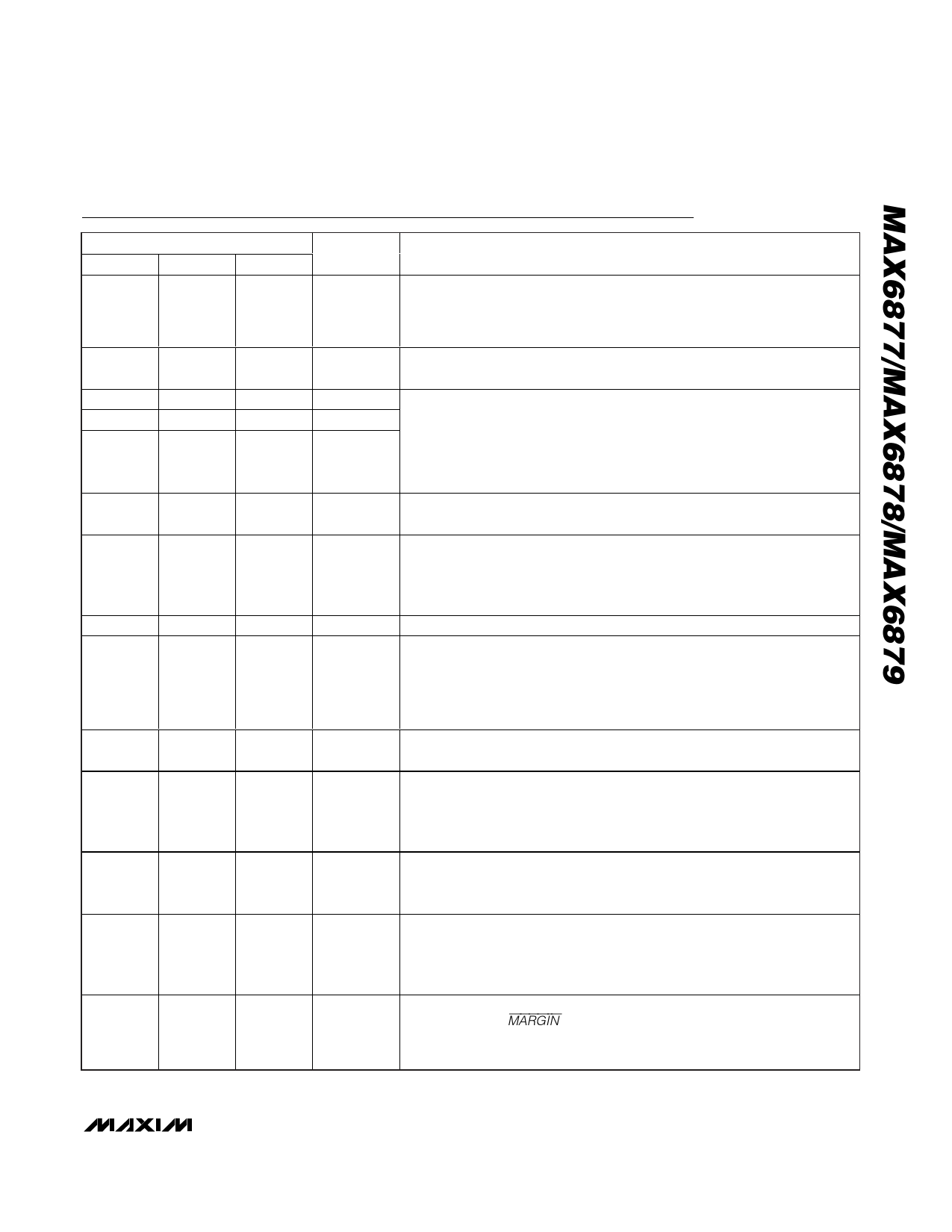
Dual-/Triple-Voltage, Power-Supply
Trackers/Sequencers/Supervisors
Pin Description
PIN
MAX6877 MAX6878 MAX6879
1
1
—
2
2
1
3
—
—
4
4
2
5
5
3
NAME
VCC
ABP
SET3
SET2
SET1
FUNCTION
Optional Supply Voltage Input. Connect VCC to an alternate (i.e., always-on)
supply if desired. Leave VCC unconnected, if not used. VCC allows IN_
supplies less than UVLO to be tracked. VCC is internally pulled down by a
100kΩ resistor.
Internal Supply Bypass Input. Bypass ABP with a 1µF capacitor to GND. ABP
maintains the device supply voltage during rapid power-down conditions.
Externally Adjusted IN_ Undervoltage Lockout Threshold. Connect SET_ to
an external resistor-divider network to set the desired undervoltage threshold
for each IN_ supply (see the Typical Application Circuit). All SET_ inputs
must be above the internal SET_ threshold (0.5V) to enable tracking or
sequencing functionality.
—
3, 16, 17,
22
—
N.C.
No Connection. Not internally connected.
Logic-Enable Input or Undervoltage Lockout Monitor Input. EN/UV must be
6
6
4
EN/UV
high (EN/UV > VEN_R) to enable voltage tracking or sequencing power-up
operation. OUT_ begins tracking down when EN/UV < VEN_F. Connect EN/UV
to an external resistor-divider network to set the external UVLO threshold.
7
7
5
GND
Ground
Tracking Startup/Sequence Delay Select Input. Connect a capacitor from
DELAY to GND to select the desired delay period before tracking is enabled
8
8
6
DELAY (after all SET_ inputs and EN/UV are above their respective thresholds) or
between supply sequences. Leave DELAY unconnected for the default
200µs delay period.
9
9
7
SLEW
Slew-Rate Adjustment Input. Connect a capacitor from SLEW to GND to
select the desired OUT_ slew rate.
PG/RST Timeout Period Adjust Input. PG/RST asserts high after the timeout
10
10
—
TIMEOUT
period when all OUT_ exceed their IN_ referenced threshold. Connect a
capacitor from TIMEOUT to GND to set the desired timeout period. Leave
TIMEOUT unconnected for the default 200µs delay period.
11
11
Latch/Autoretry Selection Input. Drive LTCH/RTR low to select the latch mode.
8
LTCH/RTR Connect LTCH/RTR to ABP or leave unconnected to select autoretry mode.
LTCH/RTR is internally pulled up to ABP through a 10µA current source.
12
12
Track/Sequence Select Input. Drive TRK/SEQ low to enable supply tracking
9
TRK/SEQ
function. Connect TRK/SEQ to ABP or leave it unconnected to enable supply
sequencing. TRK/SEQ is internally pulled to ABP through a 10µA current
source.
Margin Input, Active-Low. Drive MARGIN low to enable margin mode (see
13
13
—
MARGIN
the Margin Input (MARGIN) section). The MARGIN functionality is disabled
(returns to normal monitoring mode) after MARGIN returns high. MARGIN is
internally pulled up to ABP through a 10µA current source.
______________________________________________________________________________________ 13
Share Link: 