MAX6877 データシートの表示(PDF) - Maxim Integrated
部品番号
コンポーネント説明
メーカー
MAX6877 Datasheet PDF : 24 Pages
| |||
Dual-/Triple-Voltage, Power-Supply
Trackers/Sequencers/Supervisors
PIN
MAX6877 MAX6878 MAX6879
14
14
—
15
15
10
16
—
—
17
—
—
18
18
11
19
19
12
20
20
13
21
21
14
22
—
—
23
23
15
24
24
16
EP
EP
EP
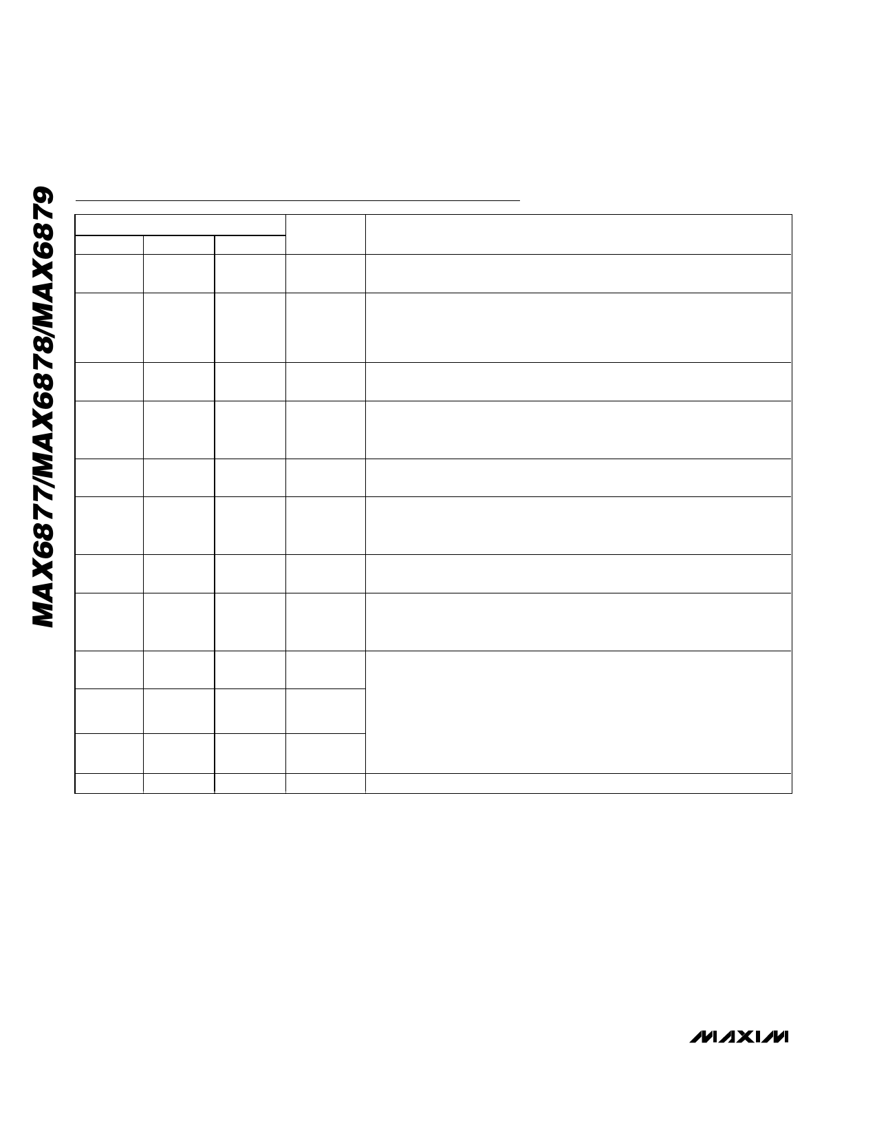
Pin Description (continued)
NAME
PG/RST
FAULT
OUT3
GATE3
OUT2
GATE2
OUT1
GATE1
IN3
IN2
IN1
EP
FUNCTION
Power-Good Output, Open-Drain. PG_RST asserts high tTIMEOUT after all
OUT_ voltages exceed the VTH_PG thresholds.
Tracking Fault Alert Output, Active Low, Open-Drain. FAULT asserts low if a
tracking failure is present for longer than the selected fault period or if
tracking voltages fail by more than ±250mV. FAULT asserts low if any OUT_
falls below the corresponding IN_ voltage.
Channel 3 Monitored Output Voltage. Connect OUT3 to the source of an n-
channel FET. A fault condition activates a 100Ω pulldown to ground.
Gate Drive for External n-Channel FET. An internal charge pump boosts
GATE3 to VIN3 + 5V to fully enhance the external n-channel FET when power-
up is complete.
Channel 2 Monitored Output Voltage. Connect OUT2 to the source of an
n-channel FET. A fault condition activates a 100Ω pulldown to ground.
Gate Drive for External n-Channel FET. An internal charge pump boosts
GATE2 to VIN2 + 5V to fully enhance the external n-channel FET when power-
up is complete.
Channel 1 Monitored Output Voltage. Connect OUT1 to the source of an
n-channel FET. A fault condition activates a 100Ω pulldown to ground.
Gate Drive for External n-Channel FET. An internal charge pump boosts
GATE1 to VIN1 + 5V to fully enhance the external n-channel FET when power-
up is complete.
Supply Input Voltage. IN1, IN2, or IN3 must be greater than the internal
undervoltage lockout (VABP = 2.7V) to enable the tracking or sequencing
functionality. Each IN_ input is simultaneously monitored by SET_ inputs to
ensure all supplies have stabilized before power-up is enabled. If IN_ is
connected to ground or left unconnected and SET_ is above 0.5V, then no-
sequencing control is performed on that channel. Each IN_ is internally
pulled down by a 100kΩ resistor.
Exposed Paddle. Connect exposed paddle to ground.
14 ______________________________________________________________________________________
Share Link: 