HT46C24 データシートの表示(PDF) - Holtek Semiconductor
部品番号
コンポーネント説明
メーカー
HT46C24 Datasheet PDF : 51 Pages
| |||
HT46R24/HT46C24
Interrupt Source
External Interrupt
Timer/Event Counter 0 Overflow
Timer/Event Counter 1 Overflow
A/D Converter Interrupt
I2C Bus Interrupt
Priority
1
2
3
4
5
Vector
04H
08H
0CH
10H
14H
The Timer/Event Counter 0/1 interrupt request flag (T0F,
T1F), external interrupt request flag (EIF), A/D converter
request flag (ADF), the I2C Bus interrupt request flag
(HIF), enable timer/event counter bit (ET0I, ET1I), en-
able external interrupt bit (EEI), enable A/D converter in-
terrupt bit (EADI), enable I2C Bus interrupt bit (EHI) and
enable master interrupt bit (EMI) constitute an interrupt
control register 0 (INTC0) and an interrupt control regis-
ter 1 (INTC1) which are located at 0BH and 1EH in the
data memory. EMI, EEI, ET0I, ET1I, EADI, EHI are used
to control the enabling/disabling of interrupts. These bits
prevent the requested interrupt from being serviced.
Once the interrupt request flags (T0F, T1F, EIF, ADF,
HIF) are set, they will remain in the INTC0 and INTC1
register until the interrupts are serviced or cleared by a
software instruction.
It is recommended that a program does not use the
²CALL subroutine² within the interrupt subroutine. Inter-
rupts often occur in an unpredictable manner or need to
be serviced immediately in some applications. If only one
stack is left and enabling the interrupt is not well con-
trolled, the original control sequence will be damaged
once the ²CALL² operates in the interrupt subroutine.
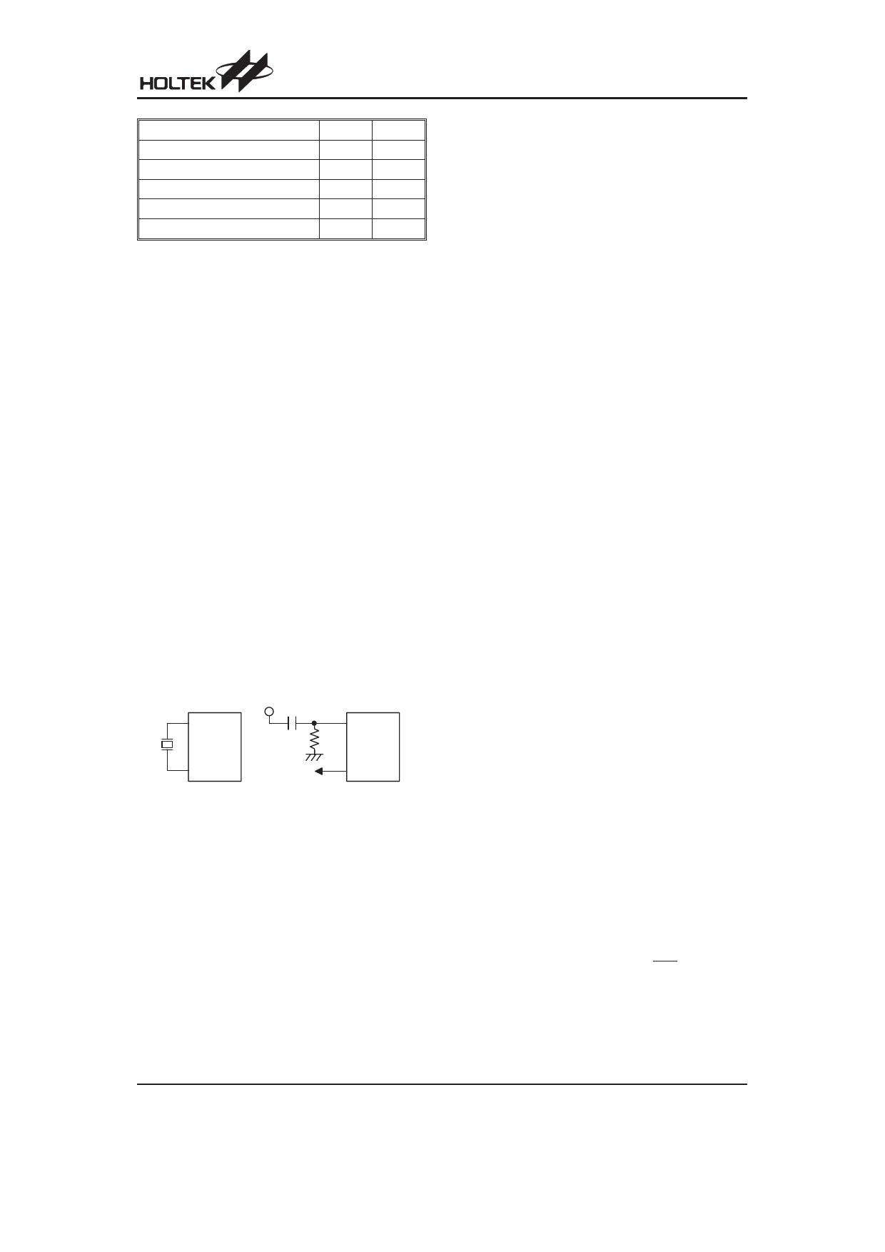
Oscillator Configuration
There are two oscillator circuits in the microcontroller.
O SC1
V DD
470pF
O SC1
O SC2
fS Y S /4
O SC2
C r y s ta l O s c illa to r
R C O s c illa to r
System Oscillator
Both are designed for system clocks, namely the RC os-
cillator and the Crystal oscillator, which are determined
by the option. No matter what oscillator type is selected,
the signal provides the system clock. The HALT mode
stops the system oscillator and ignores an external sig-
nal to conserve power.
If an RC oscillator is used, an external resistor between
OSC1 and VSS is required and the resistance must
range from 30kW to 750kW. The system clock, divided
by 4, is available on OSC2 with pull-high resistor, which
can be used to synchronize external logic. The RC os-
cillator provides the most cost effective solution. How-
ever, the frequency of oscillation may vary with VDD,
temperatures and the chip itself due to process varia-
tions. It is, therefore, not suitable for timing sensitive
operations where an accurate oscillator frequency is
desired.
If the Crystal oscillator is used, a crystal across OSC1
and OSC2 is needed to provide the feedback and phase
shift required for the oscillator, and no other external
components are required. Instead of a crystal, a resona-
tor can also be connected between OSC1 and OSC2 to
get a frequency reference, but two external capacitors in
OSC1 and OSC2 are required (If the oscillating fre-
quency is less than 1MHz).
The WDT oscillator is a free running on-chip RC oscillator,
and no external components are required. Even if the sys-
tem enters the power down mode, the system clock is
stopped, but the WDT oscillator still works with a period of
approximately 65ms at 5V. The WDT oscillator can be dis-
abled by option to conserve power.
Watchdog Timer - WDT
The WDT clock source is implemented by a dedicated
RC oscillator (WDT oscillator) or instruction clock (sys-
tem clock divided by 4) decided by options. This timer is
designed to prevent a software malfunction or sequence
jumping to an unknown location with unpredictable re-
sults. The watchdog timer can be disabled by a option. If
the watchdog timer is disabled, all the executions re-
lated to the WDT result in no operation.
Once an internal WDT oscillator (RC oscillator with pe-
riod 65ms at 5V normally) is selected, it is divided by
212~215 (by option to get the WDT time-out period). The
WDT time-out minimum period is 300ms~600ms. This
time-out period may vary with temperature, VDD and
process variations. By selection from the WDT option,
longer time-out periods can be realized. If the WDT
time-out is selected 215, the maximum time-out period is
divided by 215~216about 2.1s~4.3s.
If the WDT oscillator is disabled, the WDT clock may still
come from the instruction clock and operate in the same
manner except that in the HALT state the WDT may stop
counting and lose its protecting purpose. In this situation
the logic can only be restarted by external logic. If the
device operates in a noisy environment, using the
on-chip RC oscillator (WDT OSC) is strongly recom-
mended, since the HALT will stop the system clock.
The WDT overflow under normal operation will initialize
²chip reset² and set the status bit TO. Whereas in the
HALT mode, the overflow will initialize a ²warm reset²
only the program counter and stack pointer are reset to
zero. To clear the contents of WDT, three methods are
adopted; external reset (a low level to RES), software in-
structions, or a HALT instruction. The software instruc-
tions include CLR WDT and the other set CLR WDT1
and CLR WDT2. Of these two types of instruction, only
one can be active depending on the option - ²CLR WDT
times selection option². If the ²CLR WDT² is selected (i.e.
Rev. 2.00
11
March 2, 2006
Share Link: 