M24C16-BN3TG/W гғҮгғјгӮҝгӮ·гғјгғҲгҒ®иЎЁзӨәпјҲPDFпјү - STMicroelectronics
йғЁе“Ғз•ӘеҸ·
гӮігғігғқгғјгғҚгғігғҲиӘ¬жҳҺ
гғЎгғјгӮ«гғј
M24C16-BN3TG/W Datasheet PDF : 29 Pages
| |||
M24C16, M24C08, M24C04, M24C02, M24C01
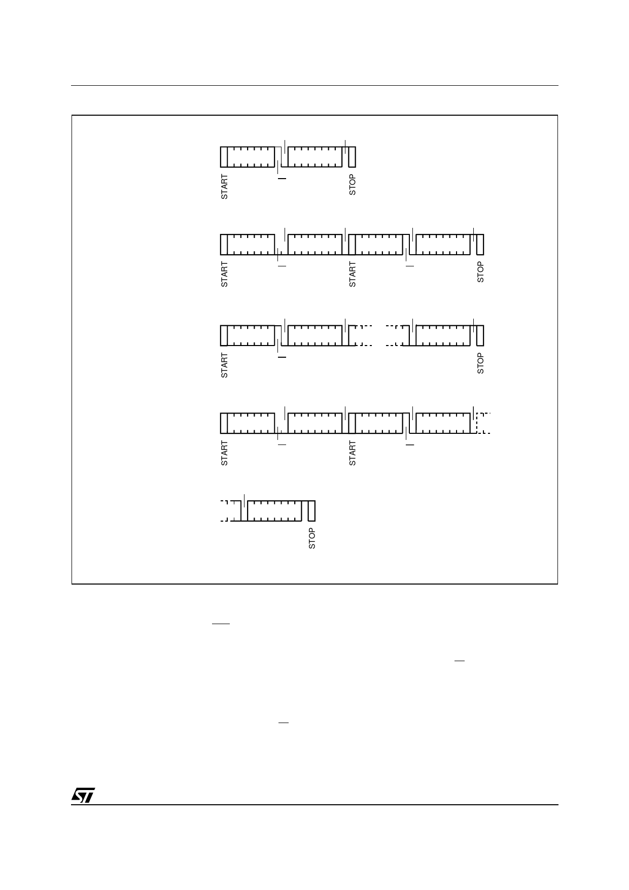
Figure 9. Read Mode Sequences
CURRENT
ADDRESS
READ
ACK
NO ACK
DEV SEL
DATA OUT
R/W
RANDOM
ADDRESS
READ
ACK
ACK
ACK
NO ACK
DEV SEL *
BYTE ADDR
DEV SEL *
DATA OUT
R/W
R/W
SEQUENTIAL
CURRENT
READ
SEQUENTIAL
RANDOM
READ
ACK
ACK
DEV SEL
DATA OUT 1
R/W
ACK
NO ACK
DATA OUT N
ACK
ACK
ACK
ACK
DEV SEL *
BYTE ADDR
DEV SEL *
DATA OUT 1
R/W
R/W
ACK
NO ACK
DATA OUT N
AI01942
Note: The seven most significant bits of the Device Select Code of a Random Read (in the 1st and 3rd bytes) must be identical.
Read Operations
Read operations are performed independently of
the state of the Write Control (WC) signal.
master must not acknowledge the byte, and termi-
nates the transfer with a Stop condition.
Current Address Read
The device has an internal address counter which
is incremented each time a byte is read.
Random Address Read
A dummy Write is first performed to load the ad-
dress into this address counter (as shown in Fig-
ure 9.) but without sending a Stop condition. Then,
the bus master sends another Start condition, and
repeats the Device Select Code, with the RW bit
set to 1. The device acknowledges this, and out-
puts the contents of the addressed byte. The bus
For the Current Address Read operation, following
a Start condition, the bus master only sends a De-
vice Select Code with the RW bit set to 1. The de-
vice acknowledges this, and outputs the byte
addressed by the internal address counter. The
counter is then incremented. The bus master ter-
minates the transfer with a Stop condition, as
shown in Figure 9., without acknowledging the
byte.
11/29
Share Link: 