M29F100 データシートの表示(PDF) - STMicroelectronics
部品番号
コンポーネント説明
メーカー
M29F100 Datasheet PDF : 30 Pages
| |||
M29F100T, M29F100B
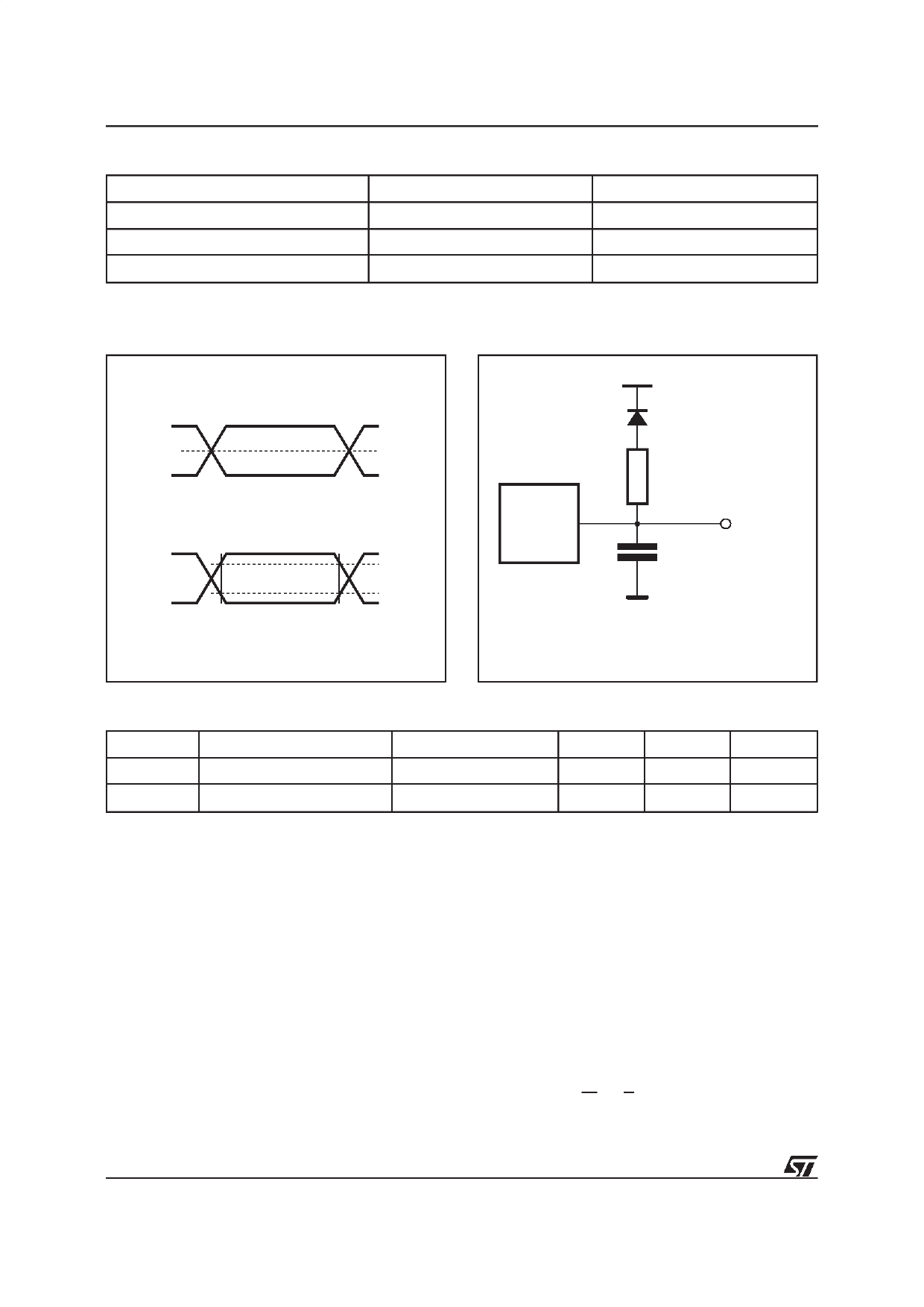
Table 11. AC Measurement Conditions
Input Rise and Fall Times
Input Pulse Voltages
Input and Output Timing Ref. Voltages
High Speed
≤ 10ns
0 to 3V
1.5V
Standard
≤ 10ns
0.45V to 2.4V
0.8V and 2V
Figure 4. AC Testing Input Output Waveform
High Speed
3V
0V
Standard
2.4V
0.45V
1.5V
2.0V
0.8V
AI01275B
Figure 5. AC Testing Load Circuit
1.3V
1N914
DEVICE
UNDER
TEST
3.3kΩ
CL
OUT
CL = 30pF for High Speed
CL = 100pF for Standard
CL includes JIG capacitance
AI01276B
Table 12. Capacitance(1) (TA = 25 °C, f = 1 MHz )
Symbol
Parameter
CIN
Input Capacitance
C OUT
Output Capacitance
Note: 1. Sampled only, not 100% tested.
Test Condition
VIN = 0V
VOUT = 0V
Min
Max
Unit
6
pF
12
pF
Block Erase (BE) Instruction. This instruction
uses a minimum of six write cycles. The Erase
Set-up command 80h is written to address AAAAh
in the Byte-wide configuration or address 5555h in
the Word-wide configuration on third cycle after the
two Coded cycles. The Block Erase Confirm com-
mand 30h is similarly written on the sixth cycle after
another two Coded cycles. During the input of the
second command an addresswithin the block to be
erased is given and latched into the memory. Addi-
tional block Erase Confirm commands and block
addresses can be written subsequently to erase
other blocks in parallel, without further Coded cy-
cles. The erase will start after the erase timeout
period (see Erase Timer Bit DQ3 description).
Thus, additional Erase Confirm commands for
other blocks must be given within this delay. The
input of a new Erase Confirm command will restart
the timeout period. The status of the internal timer
can be monitored through the level of DQ3, if DQ3
is ’0’ the Block Erase Command has been given
and the timeout is running, if DQ3 is ’1’, the timeout
has expired and the P/E.C. is erasing the Block(s).
If the second command given is not an erase
confirm or if the Coded cycles are wrong, the
instruction aborts, and the device is reset to Read
Array. It is not necessary to program the block with
00h as the P/E.C. will do this automatically before
to erasing to FFh. Read operations after the sixth
rising edge of W or E output the status register
status bits.
12/30
Share Link: 