MACH120-18JI データシートの表示(PDF) - Lattice Semiconductor
部品番号
コンポーネント説明
メーカー
MACH120-18JI Datasheet PDF : 20 Pages
| |||
ABSOLUTE MAXIMUM RATINGS
Storage Temperature . . . . . . . . . . . . . -65°C to +150°C
Ambient Temperature
With Power Applied . . . . . . . . . . . . . -55°C to +125°C
Device Junction Temperature . . . . . . . . . . . . . +150°C
Supply Voltage with
Respect to Ground . . . . . . . . . . . . . . -0.5 V to +7.0 V
DC Input Voltage . . . . . . . . . . . . -0.5 V to VCC + 0.5 V
DC Output or I/O
Pin Voltage . . . . . . . . . . . . . . . . . -0.5 V to VCC + 0.5 V
Static Discharge Voltage . . . . . . . . . . . . . . . . . 2001 V
Latchup Current
(TA = -40°C to +85°C) . . . . . . . . . . . . . . . . . . . 200 mA
Stresses above those listed under Absolute Maximum Ratings
may cause permanent device failure. Functionality at or above
these limits is not implied. Exposure to Absolute Maximum Rat-
ings for extended periods may affect device reliability. Pro-
gramming conditions may differ.
INDUSTRIAL OPERATING RANGES
Industrial (I) Devices
Ambient Temperature (TA)
Operating in Free Air . . . . . . . . . . . . . . -40°C to +85°C
Supply Voltage (VCC)
with Respect to Ground . . . . . . . . . . . +4.5 V to +5.5 V
Operating ranges define those limits between which the func-
tionality of the device is guaranteed.
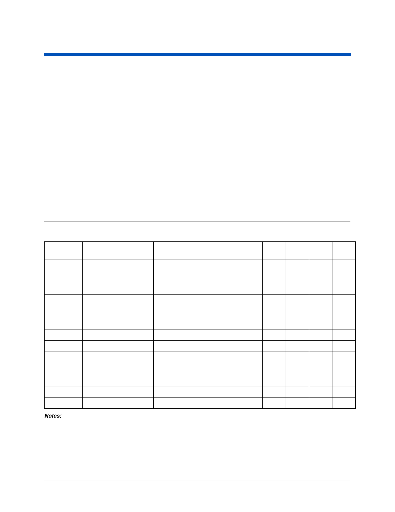
DC CHARACTERISTICS over INDUSTRIAL operating ranges
Parameter
Symbol
Parameter Description
Test Conditions
Min Typ Max Unit
VOH
Output HIGH Voltage
IOH = -3.2 mA, VCC = Min
VIN = VIH or VIL
2.4
V
VOL
Output LOW Voltage
IOL = 16 mA, VCC = Min
VIN = VIH or VIL
0.5
V
VIH
Input HIGH Voltage
Guaranteed Input Logical HIGH
Voltage for all Inputs (Note 1)
2.0
V
VIL
Input LOW Voltage
Guaranteed Input Logical LOW
Voltage for all Inputs (Note 1)
IIH
Input HIGH Current
VIN = 5.25 V, VCC = Max (Note 2)
IIL
Input LOW Current
VIN = 0 V, VCC = Max (Note 2)
IOZH
Off-State Output Leakage
Current HIGH
VOUT = 5.25 V, VCC = Max
VIN = VIH or VIL (Note 2)
IOZL
Off-State Output Leakage
Current LOW
VOUT = 0 V, VCC = Max
VIN = VIH or VIL (Note 2)
ISC
Output Short-Circuit Current VOUT = 0.5 V, VCC = Max (Note 3)
-30
ICC
Supply Current (Typical) VCC = 5 V, TA = 25°C, f = 25 MHz (Note 4)
0.8
V
10
µA
-10
µA
10
µA
-10
µA
-130
mA
85
mA
Notes:
1. These are absolute values with respect to device ground and all overshoots due to system and/or tester noise are included.
2. I/O pin leakage is the worst case of IIL and IOZL (or IIH and IOZH).
3. Not more than one output should be shorted at a time. Duration of the short-circuit should not exceed one second. VOUT = 0.5 V
has been chosen to avoid test problems caused by tester ground degradation.
4. Measured with a 12-bit up/down counter pattern. This pattern is programmed in each PAL block and is capable of being loaded,
enabled, and reset.
12
MACH120-18 (Ind)
Share Link: 