X1228 データシートの表示(PDF) - Intersil
部品番号
コンポーネント説明
メーカー
X1228 Datasheet PDF : 29 Pages
| |||
X1228
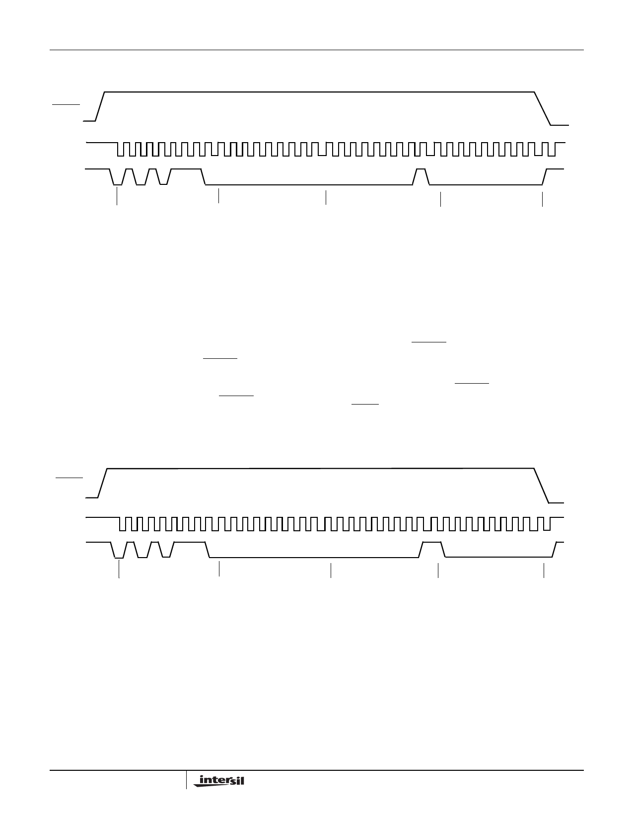
Figure 5. Set VTRIP Level Sequence (VCC = desired VTRIP value)
RESET
VCC
SCL
0 1 23 4 56 7
VP = 15V
01 23 4 56 7
01 23 4 56 7
VCC
01 23 4 56 7
SDA
AEh
00h
Note: BP0, BP1, BP2 must be disabled.
01h
00h
Resetting the VTRIP Voltage
This procedure is used to set the VTRIP to a “native”
voltage level. For example, if the current VTRIP is 4.4V
and the new VTRIP must be 4.0V, then the VTRIP must
be reset. When VTRIP is reset, the new VTRIP is some-
thing less than 1.7V. This procedure must be used to
set the voltage to a lower value.
To reset the new VTRIP voltage, apply more than 5.5V
to the VCC pin and tie the RESET pin to the
programming voltage VP. Then write 00h to address
03h. The stop bit of a valid write operation initiates the
VTRIP programming sequence. Bring RESET to VCC to
complete the operation. Note: this operation takes up
Figure 6. Reset VTRIP Level Sequence
to 10 milliseconds to complete and also writes 00h to
address 03h of the EEPROM array.
For best accuracy in setting VTRIP, it is advised that
the following sequence be used.
1.Program VTRIP as above.
2.Measure resulting VTRIP by measuring the VCC
value where a RESET occurs. Calculate Delta =
(Desired – Measured) VTRIP value.
3.Perform a VTRIP program using the following formula
to set the voltage of the RESET pin:
VRESET = (Desired Value – Delta) + 0.025V
RESET
VCC
SCL
VP = 15V
VCC
0 1 23 4 56 7
01 23 4 56 7
01 23 4 56 7
01 23 4 56 7
SDA
AEh
00h
03h
00h
Note: BP0, BP1, BP2 must be disabled.
17
FN8100.4
May 18, 2006
Share Link: 