MAX6872 データシートの表示(PDF) - Maxim Integrated
部品番号
コンポーネント説明
メーカー
MAX6872 Datasheet PDF : 48 Pages
| |||
EEPROM-Programmable, Hex/Quad,
Power-Supply Sequencers/Supervisors
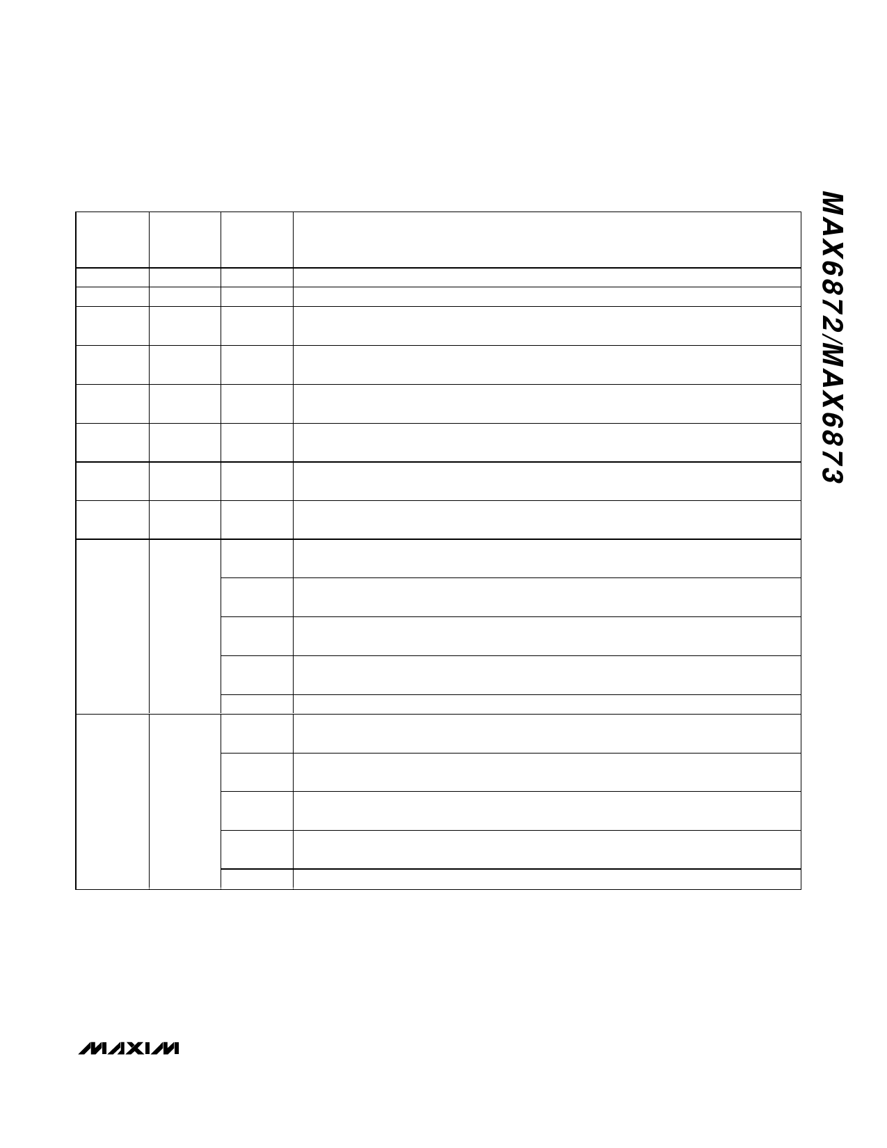
Table 4. IN3–IN6 Threshold Settings
REGISTER
ADDRESS
EEPROM
MEMORY
ADDRESS
02h
8002h
03h
8003h
04h
8004h
05h
8005h
08h
8008h
09h
8009h
0Ah
800Ah
0Bh
800Bh
0Ch
800Ch
0Dh
800Dh
BIT
RANGE
[7:0]
[7:0]
[7:0]
[7:0]
[7:0]
[7:0]
[7:0]
[7:0]
[2]
[3]
[4]
[5]
[7:6]
[1]
[2]
[3]
[4]
[5]
DESCRIPTION
IN3 primary undervoltage detector threshold (V3A) (see equations in the IN3–IN6 section).
IN4 primary undervoltage detector threshold (V4A) (see equations in the IN3–IN6 section).
IN5 (MAX6872 only) primary undervoltage detector threshold (V5A)
(see equations in the IN3–IN6 section).
IN6 (MAX6872 only) primary undervoltage detector threshold (V6A)
(see equations in the IN3–IN6 section).
IN3 secondary undervoltage/overvoltage detector threshold (V3B)
(see equations in the IN3–IN6 section).
IN4 secondary undervoltage/overvoltage detector threshold (V4B)
(see equations in the IN3–IN6 section).
IN5 (MAX6872 only) secondary undervoltage/overvoltage detector threshold (V5B)
(see equations in the IN3–IN6 section).
IN6 (MAX6872 only) secondary undervoltage/overvoltage detector threshold (V6B)
(see equations in the IN3–IN6 section).
IN3 secondary overvoltage/undervoltage selection.
0 = overvoltage threshold. 1 = undervoltage threshold.
IN4 secondary overvoltage/undervoltage selection.
0 = overvoltage threshold. 1 = undervoltage threshold.
IN5 (MAX6872 only) secondary overvoltage/undervoltage selection.
0 = overvoltage threshold. 1 = undervoltage threshold.
IN6 (MAX6872 only) secondary overvoltage/undervoltage selection.
0 = overvoltage threshold. 1 = undervoltage threshold.
Not used.
IN3 range selection.
0 = +1V to +5.5V range in 20mV increments. 1 = +0.5V to +3.05V range in 10mV increments.
IN4 range selection.
0 = +1V to +5.5V range in 20mV increments. 1 = +0.5V to +3.05V range in 10mV increments.
IN5 (MAX6872 only) range selection.
0 = +1V to +5.5V range in 20mV increments. 1 = +0.5V to +3.05V range in 10mV increments.
IN6 (MAX6872 only) range selection.
0 = +1V to +5.5V range in 20mV increments. 1 = +0.5V to +3.05V range in 10mV increments.
Not used.
erwise the threshold exceeds the maximum operating
voltage of IN3–IN6.
GPI1–GPI4
The GPI1–GPI4 programmable logic inputs control
power-supply sequencing (programmable outputs),
reset/interrupt signaling, and watchdog functions (see
the Configuring the Watchdog Timers (Registers
3Ch–3Fh) section). Configure GPI1–GPI4 for active-low
or active-high logic (Table 5). GPI1–GPI4 internally pull
down to GND through a 10µA current sink.
______________________________________________________________________________________ 15
Share Link: 