MAX6872 データシートの表示(PDF) - Maxim Integrated
部品番号
コンポーネント説明
メーカー
MAX6872 Datasheet PDF : 48 Pages
| |||
EEPROM-Programmable, Hex/Quad,
Power-Supply Sequencers/Supervisors
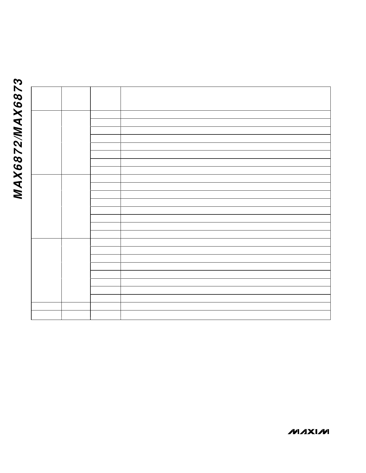
Table 8. PO1 (MAX6872 Only) Output Dependency
REGISTER
ADDRESS
EEPROM
MEMORY
ADDRESS
BIT
OUTPUT ASSERTION CONDITIONS
0Eh
800Eh
0Fh
800Fh
10h
8010h
11h
8011h
40h
8040h
[0]
1 = PO1 assertion depends on IN1 primary undervoltage threshold (Table 2).
[1]
1 = PO1 assertion depends on IN2 primary undervoltage threshold (Table 3).
[2]
1 = PO1 assertion depends on IN3 primary undervoltage threshold (Table 4).
[3]
1 = PO1 assertion depends on IN4 primary undervoltage threshold (Table 4).
[4]
1 = PO1 assertion depends on IN5 primary undervoltage threshold (Table 4).
[5]
1 = PO1 assertion depends on IN6 primary undervoltage threshold (Table 4).
[6]
1 = PO1 assertion depends on watchdog 1 (Tables 25 and 26).
[7]
1 = PO1 assertion depends on watchdog 2 (Tables 25 and 26).
[0]
1 = PO1 assertion depends on IN1 secondary undervoltage/overvoltage threshold (Table 2).
[1]
1 = PO1 assertion depends on IN2 secondary undervoltage/overvoltage threshold (Table 3).
[2]
1 = PO1 assertion depends on IN3 secondary undervoltage/overvoltage threshold (Table 4).
[3]
1 = PO1 assertion depends on IN4 secondary undervoltage/overvoltage threshold (Table 4).
[4]
1 = PO1 assertion depends on IN5 secondary undervoltage/overvoltage threshold (Table 4).
[5]
1 = PO1 assertion depends on IN6 secondary undervoltage/overvoltage threshold (Table 4).
[6]
1 = PO1 assertion depends on GPI1 (Table 5).
[7]
1 = PO1 assertion depends on GPI2 (Table 5).
[0]
1 = PO1 assertion depends on GPI3 (Table 5).
[1]
1 = PO1 assertion depends on GPI4 (Table 5).
[2]
1 = PO1 assertion depends on PO2 (Table 9).
[3]
1 = PO1 assertion depends on PO3 (Tables 10 and 11).
[4]
1 = PO1 assertion depends on PO4 (Tables 12 and 13).
[5]
1 = PO1 assertion depends on PO5 (Tables 14 and 15).
[6]
1 = PO1 assertion depends on PO6 (Tables 16 and 17).
[7]
1 = PO1 assertion depends on PO7 (Table 18).
[0]
1 = PO1 assertion depends on PO8 (Table 19).
[0]
1 = PO1 asserts when MR = low (Table 6).
for each programmable output. See register 3Ah (Table
20) to set the active state (active-high or active-low) for
each programmable output and registers 11h, 15h,
1Ch, 23h, 2Ah, 31h, 35h, and 39h to select the output
stage types (Tables 21 and 22), and PO_ timeout peri-
ods (Table 23) for each output.
Control selected programmable outputs with a sum of
products (Tables 8–19). Each product allows a different
set of conditions to assert each output. Outputs PO3
(MAX6872)/PO1 (MAX6873) and PO6 (MAX6872)/
PO4 (MAX6873) allow two sets of different conditions to
assert each output. Outputs PO1 and PO2 (MAX6872
only), PO7 (MAX6872)/PO5 (MAX6873), and PO8
(MAX6872 only) allow only one set of conditions to
assert each output.
For example, Product 1 of the PO3 (MAX6872—Table
10) programmable output may depend on the IN1 pri-
mary undervoltage threshold, and the states of GPI1,
PO1, and PO2. Write a one to R16h[0], R17h[6], and
R18h[3:2] to configure Product 1 as indicated. IN1
must be above the primary undervoltage threshold
(Table 2), GPI1 must be inactive (Table 5), and PO1
(Tables 8 and 20) and PO2 (Tables 10 and 21) must
be in their deasserted states for Product 1 to be a logi-
cal 1. Product 1 is equivalent to the logic statement:
V1A • GPI1 • PO1 • PO2.
Product 2 of PO3 (MAX6872, Table 11) may depend on
an entirely different set of conditions, or the same condi-
tions, depending on the system requirements. For
example, Product 2 may depend on the IN1 undervolt-
18 ______________________________________________________________________________________
Share Link: 