MAX6872 データシートの表示(PDF) - Maxim Integrated
部品番号
コンポーネント説明
メーカー
MAX6872 Datasheet PDF : 48 Pages
| |||
EEPROM-Programmable, Hex/Quad,
Power-Supply Sequencers/Supervisors
MR
The manual reset (MR) input initiates a reset condi-
tion. Register 40h determines the programmable out-
puts that assert while MR is low (Table 6). All affected
programmable outputs remain asserted (see the
Programmable Outputs section) for their PO_ timeout
periods after MR releases high. An internal 10µA cur-
rent source pulls MR to DBP. Leave MR unconnected
or connect to DBP if unused. A programmable output
cannot depend solely on MR.
MARGIN
MARGIN allows system-level testing while power sup-
plies exceed the normal ranges. Registers 41h and
42h determine whether the programmable outputs
assert to a predetermined state or hold the last state
as MARGIN is driven low (Table 7). Drive MARGIN low
to set the programmable outputs in a known state
while system-level testing occurs. Leave MARGIN
unconnected or connect to DBP if unused. An internal
10µA current source pulls MARGIN to DBP. The state
of each programmable output does not change while
MARGIN = GND. MARGIN overrides MR if both assert
at the same time.
Programmable Outputs
The MAX6872 features eight programmable outputs,
while the MAX6873 features five programmable outputs.
Selectable output-stage configurations include: active low
or active high, open drain, weak pullup, push-pull, or
charge pump. During power-up, the programmable out-
puts pull to GND with an internal 10µA current sink for 1V
< VABP < VUVLO. The programmable outputs remain in
their active states until their respective PO_ timeout peri-
ods expire, and all of the programmed conditions are met
for each output. Any output programmed to depend on
no condition always remains in its active state (Table 20).
An active-high configured output is considered asserted
Table 5. GPI1–GPI4 Active Logic States
REGISTER
ADDRESS
3Bh
EEPROM
MEMORY
ADDRESS
803Bh
BIT RANGE
DESCRIPTION
[0]
GPI1. 0 = active low. 1 = active high.
[1]
GPI2. 0 = active low. 1 = active high.
[2]
GPI3. 0 = active low. 1 = active high.
[3]
GPI4. 0 = active low. 1 = active high.
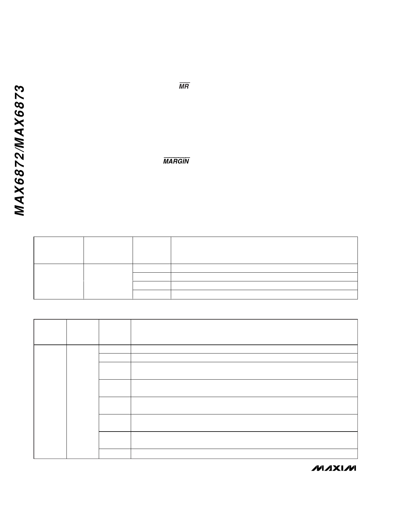
Table 6. Programmable Output Behavior and MR
REGISTER
ADDRESS
EEPROM
MEMORY
ADDRESS
BIT
RANGE
DESCRIPTION
40h
8040h
[0]
PO1 (MAX6872 only). 0 = PO1 independent of MR. 1 = PO1 asserts when MR = low.
[1]
PO2 (MAX6872 only). 0 = PO2 independent of MR. 1 = PO2 asserts when MR = low.
[2]
PO3 (MAX6872)/PO1 (MAX6873). 0 = PO3/PO1 independent of MR.
1 = PO3/PO1 asserts when MR = low.
[3]
PO4 (MAX6872)/PO2 (MAX6873). 0 = PO4/PO2 independent of MR.
1 = PO4/PO2 asserts when MR = low.
[4]
PO5 (MAX6872)/PO3 (MAX6873). 0 = PO5/PO3 independent of MR.
1 = PO5/PO3 asserts when MR = low.
[5]
PO6 (MAX6872)/PO4 (MAX6873). 0 = PO6/PO4 independent of MR.
1 = PO6/PO4 asserts when MR = low.
[6]
PO7 (MAX6872)/PO5 (MAX6873). 0 = PO7/PO5 independent of MR.
1 = PO7/PO5 asserts when MR = low.
[7]
PO8 (MAX6872 only). 0 = PO8 independent of MR. 1 = PO8 asserts when MR = low.
16 ______________________________________________________________________________________
Share Link: 