CS61583 データシートの表示(PDF) - Cirrus Logic
部品番号
コンポーネント説明
メーカー
CS61583 Datasheet PDF : 44 Pages
| |||
CS61583
instruction register and all test data registers re-
tain their previous state. When J-TMS is high
and a rising edge is applied to J-TCK, the con-
troller moves to the Select-DR state.
When the TAP controller is in this state and a
rising edge is applied to J-TCK, the controller
enters the Exit1-DR state if J-TMS is high or the
Shift-DR state if J-TMS is low.
Select-DR-Scan State
This is a temporary controller state. The test
data register selected by the current instruction
retains its previous state. If J-TMS is held low
and a rising edge is applied to J-TCK when in
this state, the controller moves into the Capture-
DR state and a scan sequence for the selected
test data register is initiated. If J-TMS is held
high and a rising edge applied to J-TCK, the
controller moves to the Select-IR-Scan state.
The instruction does not change in this state.
Capture-DR State
In this state, the Boundary Scan Register cap-
tures input pin data if the current instruction is
EXTEST or SAMPLE/PRELOAD. The other
test data registers, which do not have parallel in-
put, are not changed.
The instruction does not change in this state.
Shift-DR State
In this controller state, the test data register con-
nected between J-TDI and J-TDO as a result of
the current instruction shifts data on stage to-
ward its serial output on each rising edge of
J-TCK.
The instruction does not change in this state.
When the TAP controller is in this state and a
rising edge is applied to J-TCK, the controller
enters the Exit1-DR state if J-TMS is high or re-
mains in the Shift-DR state if J-TMS is low.
Exit1-DR State
This is a temporary state. While in this state, if
J-TMS is held high, a rising edge applied to J-
TCK causes the controller to enter the
Update-DR state, which terminates the scanning
process. If J-TMS is held low and a rising edge
is applied to J-TCK, the controller enters the
Pause-DR state.
1
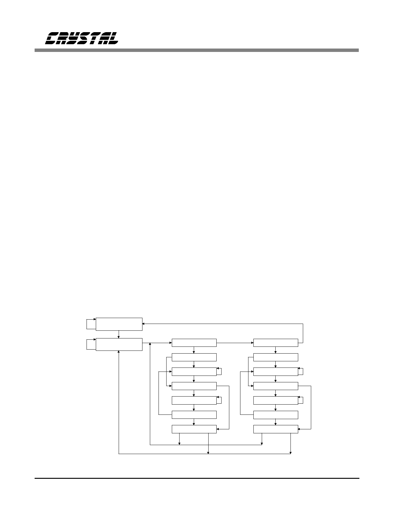
Test-Logic-Reset
0
1
0
Run-Test/Idle
Select-DR-Scan 1
0
1
Capture-DR
0
Shift-DR
0
1
1
Exit1-DR
0
Pause-DR
0
1
0
Exit2-DR
1
Update-DR
1
0
Select-IR-Scan 1
0
1
Capture-IR
0
Shift-IR
0
1
1
Exit1-IR
0
Pause-IR
0
1
0
Exit2-IR
1
Update-IR
1
0
Figure 12. TAP Controller State Diagram
18
DS172PP5
Share Link: 